|
Shenzhen JFY Tech. Co., Ltd.
|


Wall mounted 30KW dc quick EV charging station with OCPP1.6J
| Price: | 5000.0 USD |
| Payment Terms: | T/T |
| Place of Origin: | Guangdong, China (Mainland) |
|
|
|
| Add to My Favorites | |
| HiSupplier Escrow |
Product Detail
It can serve as the fast DC power supply for on-board chargers or the vehicles with a DC fast charging port based on CCS.
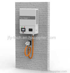
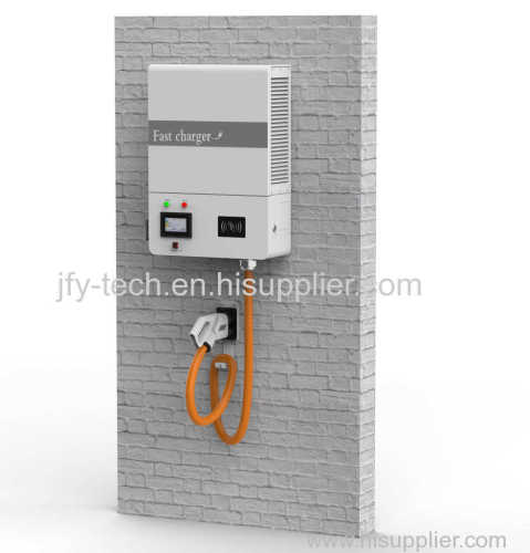
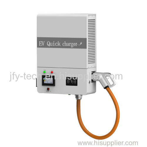
Wall mounted 30KW dc quick EV charging station with OCPP1.6J
II. Overview of product
2.1 Product Introduction
The CSW series wall mounted DC fast charger is portable DC charger with resistance to vibration, complete protection function, which is suitable for harsh outdoor environment and emergency scenarios. It is suitable for bus charging stations, parking lots, auto repair shops, car manufacturers, etc, which is convenient for customers to quickly respond, test and charge vehicles. It can effectively charge the vehicles unable to be charged by other chargers due to incompatibility. It can serve as the fast DC power supply for on-board chargers or the vehicles with a DC fast charging port based on CCS.
2.2 Product features:
Main functions
· Automatic charging mode: The charging parameters of the charging piles can be dynamically adjusted based on the data provided by the BMS, in response to which the charging piles performs corresponding actions in the charging process.
· Capable of communicating with BMS through PLC network, it can be used to judge the battery type, collect the parameters of the battery system and identify the battery status parameters before charging and during charging. It can communicate with the background monitoring system of the charging power station via Ethernet, upload the battery conditions, working status, working parameters, fault alarm information of the charger. It receives the control commands from the monitoring system and execute remote operations.
· Equipped with a resistive touch screen, which can display characters in a clear, complete and readable manner. The contents displayed can be identified without the external light source.
Sound safety protection:
· With sophisticated charging protection, overcharging of vehicles can be effectively prevented, which is highly safe for vehicles and people.
· The charging piles are designed with protection against lightning, current leakage, short circuit, over current, overheating and reverse connection of battery polarities.
· The charging piles are capable of protection against input over/under voltage, connection fault, emergency stop, etc.
· It is capable of insulation detection, so the charging will be automatically stopped when the insulation performance is lowered to ensure the safety of the equipment and people.
Flexibility:
· With modular design and flexible configuration, it is adaptable to various voltage levels and current levels and features high system reliability
· It has multiple flexible charging modes such as Time mode, amount, power, automatic charging and power (commissioning mode).
· It can be wired and installed flexibly and quickly, which provides a variety of networking options.
High adaptability:
· Small footprint and portable.
· Applicable to places such as bus charging stations, parking lots, auto repair shops, car dealers and auto works etc., which is convenient for customers to quickly respond, charge and test energy as the supplementary power supply.
2.3 Technical parameters
Parameter Description | Parameter values | |||||||||||||
CSW 15K500-E | CSW 30K500-E | CSW 15K7500-E | CSW 30K750-E | |||||||||||
AC input voltage | 400Vac±10% | |||||||||||||
AC power frequency | 45~65Hz | |||||||||||||
Input power factor | >0.99 | |||||||||||||
Rated output power | ≤15kw | ≤30kw | ≤15kw | ≤30kw | ||||||||||
Output voltage range | 100~500VDC | 200~750VDC | ||||||||||||
Output current | ≤40A | ≤80A | ≤37.5A | ≤75A | ||||||||||
Stabilized current precision | ±0.5% | |||||||||||||
Output current error | ≤±1%(≥30A ); ≤0.3A(<30A ) | |||||||||||||
Output voltage error | ±0.5% | |||||||||||||
Efficiency | ≥94% | |||||||||||||
Total harmonic factor | THD<5% | |||||||||||||
Optional mode | "Automatic charging mode", "Time mode", "Energy mode", "Amount mode", "Pre-set mode" | |||||||||||||
Start-up mode | Check-in with password, Check-in with card (optional) | |||||||||||||
Communication with the background | GPRS /LAN/Wi-Fi | |||||||||||||
Noise | ≤55dB | |||||||||||||
Protection rating | IP32 | |||||||||||||
Standby power consumption | ≤0.15% rated output power | |||||||||||||
DC plugs | IEC62196-3(CCS Combo 2) | |||||||||||||
2.4 Environmental conditions
Allowable ambient temperature range | -20℃~+60℃(derated for temperature higher than 50 ° C) |
Cooling method | Air cooled |
Allowable relative humidity | 5% ~95% (without condensation) |
Allowable maximum altitude | 6,000 meters (derated for altitude higher than 3,000 meters) |
2.5 Structure of wall mounted DC fast charger
Model | W (Width) | D (Depth) | H (Height) | Wight(kg) |
CSW 15K500-E | 500 | 300 | 765 | 50 |
CSW 30K500-E | 500 | 300 | 765 | 68 |
CSW 15K750-E | 500 | 300 | 765 | 50 |
CSW 30K750-E | 500 | 300 | 765 | 68 |
2.5.1Parts
l LED indicator
Name | Color | Description |
OPERATION | Yellow | Charging, yellow indicator on; charging stopped, yellow indicator off. |
FAULT | Red | Faulty, red indicator on; fault eliminated, red indicator off. |
l LCD touch screen
The user can view the operation information of the charger on the touch screen, as well as performing some control operations as follows:
1. Controlling operation of the charger
2. Displaying the running data in real time
3. Displaying fault information
4. Setting parameters
5. Viewing the operation history
Refer to the LCD operating guide for the use of LCD touch screen.
Emergency stop switch
In the event of an emergency such as a fire or an earthquake, the switch can be used to switch on or off the charging piles.
For switch off the charger under normal circumstances, press the "On/Off" button on the touch screen. Press the "Emergency stop switch" only in emergency situations, such as fire and earthquake. Do not press this button under normal conditions.
l AC input and output switch
The AC input switch is used to control the connection and disconnection between the charger and the grid. The AC breaker shall be kept in the "ON" position during normal operation. When the charger is turned off for wiring maintenance, the AC breaker shall be kept in the "OFF" position.
When the charger is turned off for wiring maintenance, the AC breaker shall be kept in the "OFF" position.
2.6 Wiring diagram
2.6.1 System block diagram
2.6.2 Electrical schematic diagram
2.7 Introduction of functions
2.7.1 MMI
There are two optional charging modes: Automatic charging mode and manual charging mode.
· Automatic charging mode: The charging parameters of the charging piles can be dynamically adjusted based on the data provided by the BMS, in response to which the charging piles performs corresponding actions in the charging process.
· Manual charging mode: The charging pile can be set manually to charge by time, by amount, by energy and by power, and there is clear operation instructions presented on the interface.
· Displaying output: The charging voltage, charging current, SOC, charging time, metering and billing, battery power information and other information are displayed in real time.
· Displaying the manual input information during manual setting.
· Displaying the corresponding prompt message in case a fault occurs.
· Displaying the relevant information in each state of the charger, and other relevant information from the monitoring unit.
· Displaying the battery power in the electric vehicles.
2.7.2 Parameter setting
The charger can receive the parameter setting command from the partition monitoring terminal. The operator can access the setting interface by entering the password to set parameters such as over/under-voltage protection threshold, over-current protection threshold, main station/pile IP and communication port.
2.7.3 Data transmission and storage
The charging pile is equipped with the data transmission interface, via which the operation and billing data, the fault data of the charger are uploaded. The transaction data are stored in a non-volatile memory in the form of a record to ensure that the stored data are correct, continuous, complete and valid. The transaction data are retained and the charging pile can collect data in time.
2.7.4 Alarm function
In case of DC output fault, power module alarm/fault, DC output over/under voltage, DC output over-current of the charger, tripped switch at the input side of the charger, interruption of communication between charge monitoring unit and partition monitoring module, monitoring unit failure, etc. the monitoring unit will trigger audio and visual alarms, which will be shown on the display through the communication port.
III. Setting the address of charging pile module
Each charging module in the charging pile has a unique address, which shall be set strictly according to the relevant requirements for setting addresses; otherwise the charging pile cannot operate normally.
3.1 Allocation of charging pile's address
To check the address of the module, open the front door of the charging pile, and you can see the compartment of the charging module. The address of the module is printed on the left side of the compartment, and the corresponding Arabic numerals are printed as shown in the figure above.
You can find the location of the module address as shown in the above figure. "Open the right door of the 30K charger"; when the front door of the charger is opened, you can see the compartment of the charger module. The address DIP diagram of the module is attached to the rear cover. The address of the module is 1 to 2 respectively from left to right. The address of modules in other models are similar to that of the 30K charger.
3.2 Location of DIP switches on the module
The DIP switches on each charging module are located as shown in the figure below:
Diagram showing the location of address switch
Related Search
Find more related products in following catalogs on Hisupplier.com
Company Info
Shenzhen JFY Tech. Co., Ltd. [China (Mainland)]
Business Type:Manufacturer
City: Shenzhen
Province/State: Guangdong
Country/Region: China (Mainland)